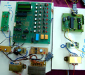
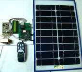
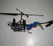
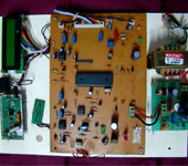
MICROCONTROLLER PROJECTS new (2011)
Some New Projects Added in 2010
- BLUETHOOTH BASED HOME AUTOMATIONl
- BLUETHOOTH BASED DATA COMMUNICATION
- CLASS ROOM ADDRESSING SYSTEM
- RESTARURANT ORDERIN SYSTEM
- MINES DETECTOR ROBOT
- AUTOMATIC RAIRWAY CROSSING GATE CONTROLLER AND TRACK SWITCHING
150 Watt amplifier circuit
150 Watt amplifier circuit
Description
This is the cheapest 150 Watt amplifier circuit you can get,I think.Based on two Darlington power transistors TIP 142 and TIP 147 ,this circuit can deliver a blasting 150 W Rms to a 4 Ohm speaker.Enough for you to get rocked?,then try out this.
TIP 147 and 142 are complementary Darlington pair transistors which can handle 5 A current and 100V ,famous for their ruggedness. Here two BC 558 transistorsQ5 and Q6 are wired as pre amplifier and TIP 142 ,TIP 147 together with TIP42 (Q1,Q2,Q3) for driving the transistors.This circuit is designed so rugged that this can be assembled even on a common board or even by pin to pin soldering.The circuit can be powered from a +/-45V 5A dual power supply.You must try this circuit.Its working great.
Circuit Diagram & Parts List .
Notes.
- Remember TIP 142 and 147 are Darlington pairs .They are shown as conventional transistors in figure for ease.So don’t get confused.Even though each of them have 2 transistors ,2 resistors and 1 diode inside ,only three pins ,base emitter and collector are coming out.Rest are connected internally.So its quite OK to assume each of them as transistor for ease.
- Use a well regulated and filtered power supply.
- Connect a 10K POT in series with the input as volume control if you need.Not shown in circuit diagram.
TIP 142 & 147 Internal diagram and pin out.
www.indianengineer.wordpress.com
www.indianengineer.wordpress.com
email Us at
Freshersblog@gmail.com
100 Watt inverter circuit
100 Watt inverter circuit
100 Watt inverter circuit
Description
Here is a 100 Watt inverter circuit using minimum number of components.I think it is quite difficult to make a decent one like this with further less components.Here we use CD 4047 IC from Texas Instruments for generating the 100 Hz pulses and four 2N3055 transistors for driving the load.
The IC1 Cd4047 wired as an astable multivibrator produces two 180 degree out of phase 100 Hz pulse trains.These pulse trains are are preamplifes by the two TIP122 transistors.The out puts of the TIP 122 transistors are amplified by four 2N 3055 transistors (two transistors for each half cycle) to drive the inverter transformer.The 220V AC will be available at the secondary of the transformer.Nothing complex just the elementary inverter principle and the circuit works great for small loads like a few bulbs or fans.If you need just a low cost inverter in the region of 100 W,then this is the best.
Circuit Diagram with Parts List.
Notes.
- A 12 V car battery can be used as the 12V source.
- Use the POT R1 to set the output frequency to50Hz.
- For the transformer get a 9-0-9 V , 10A step down transformer.But here the 9-0-9 V winding will be the primary and 220V winding will be the secondary.
- If you could not get a 10A rated transformer , don’t worry a 5A one will be just enough. But the allowed out put power will be reduced to 60W.
- Use a 10 A fuse in series with the battery as shown in circuit.
- Mount the IC on an IC holder.
- Remember,this circuit is nothing when compared to advanced PWM inverters.This is a low cost circuit meant for low scale applications.
Design Tips.
The maximum allowed output power of an inverter depends on two factors.The maximum current rating of the transformer primary and the current rating of the driving transistors.
For example ,to get a 100 Watt output using 12 V car battery the primary current will be ~8A ,(100/12) because P=VxI.So the primary of transformer must be rated above 8A.
Also here ,each final driver transistors must be rated above 4A. Here two will be conducting parallel in each half cycle, so I=8/2 = 4A .
These are only rough calculations and enough for this circuit.
WWW.IndianEngineer.wordpress.com
Email FreshersBlog@gmail.com
Biggest Project Service Provider in Delhi
All Types of Projects for all Branches are Available
Remote toggle switch circuit
Remote toggle switch circuit
Remote toggle switch circuit
Description.
In application level this circuit is similar to that of the circuit given previously. The only difference is in the approach. This circuit is designed by using another method. Using this circuit you can toggle any electrical appliance between ON and OFF states by using your TV remote. The only requirement is that your TV remote should be operating in the 38 KHz.
The IC1 (TSOP 1738) is used to receive the infrared signals from the remote. When no IR signal from remote is falling on IC1, its output will be high. When the IR signal from the remote falls on the IC1, its output goes low. This triggers the IC2 which is wired as a monostable multivibrator.The output of the IC2 (pin6) goes high for a time of 1S (set by the values of R2 and C3.This triggers the flip flop (IC2) and its Q output (pin 15) goes high. This switches on the transistor, which activates the relay and the appliance connected via relay is switched ON. For the next press of remote the IC1 will be again triggered which in turn makes the IC2 to toggle its output to low state. The load will be switched OFF. This cycle continues for each press of the remote. The pin 6 and pin 4 of IC1 are shorted to avoid false triggering.The diode D1 can be used as a freewheeling diode.
Circuit diagram with Parts list.
Notes.
- Assemble the circuit on a good quality PCB or common board.
- The circuit can be powered from a 5V DC regulated power supply.
- The capacitors must be rated 15 V.
- The IC1&IC2 must be mounted on holders.
- The current capacity of relay determines the load circuit can switch.Use a high amperage(`10A or above) relay for driving large loads like motor,heater etc.
To Get this Project Contact Us or leave us an Email
At freshersblog@gmail.com.
or Call us at 9717408885
Remote controlled appliance switch circuit
Remote controlled appliance switch circuit
Description.
Here is a versatile remote controlled appliance switch that can ON or OFF any appliance connected to it using a TV remote.
IR remote sensor IC TSOP 1738 is used for recieving the signal. Normally when no signal is falling on IC3 the output of it will be high.This makes Q1 OFF.When a signal of 38 KHz from the TV remote falls on the IC3 its output goes low.This makes Q1 conduct and a negative pulse is obtained at pin 2 of IC 1 NE 555.Due to this IC1 wired as a monostable multivibrator produces a 4 Sec long high signal at its out put.This high out put is the clock for IC 2 which is wired as a Flipflop and of , its two outputs pin 3 goes low and pin 2 goes high.The high output at pin 2 is amplified to drive the relay .For the next signal the outputs of IC2 toggles state. Result, we get a relay toggling on each press on the remote.Any appliance connected to this circuit can be switched ON or OFF.
Circuit Diagram with Parts List .
Notes.
- Before wiring the circuit make sure that the carrier frequency of the TV remote you have is 38 KHz.For that wire the sensor part only ,point your remote to the TSOP1738 and press any switch.If out put of TSOP1738 goes low them ok, your remote is of 38Khz type.Nothing to worry almost all TV remote are of this type.
- You can use any switch because for any switch the code only changes,the carrier frequency remains same.We need this carrier frequency only.
- Assemble the circuit on a good quality PCB or common board.
- The appliance can be connected through NO or NC and contacts of the relay .
www.indianengineer.wordpress.com
email freshersblog@gmail.com
Go to contact us page to contact Us or leave us an email.
We Deals in Projects Kits,circuits,models,presentations,training kits,
Wanna Buy this projects call Us. 9717408885
Low cost projects only at indianEngineer’s
Radio Collar Transmitter
Radio Collar Transmitter
Description
This is the circuit diagram of a radio transmitter suitable for fitting on radio collars.The circuit transmits a pulse in the FM between band 88MHz to 105Mhz , which can be adjusted.IC Ne 555 is wired as an astable multivibrator for producing the tone.L1 ,C3 and Q1 forms the modulator.Q2 performs the final power amplification.
Notes
For the inductor make 5 turns of .5 mm dia insulated copper wire on a standard ball pen refill.Remove the refill and make a tap at the center of coil.To vary transmission frequency experiment with number of turns.Carefull! what ever may be the no of turns the tap must be at center.Use a 50 Cm long insulated copper wire as antenna.
Parts List
R1…………………………………. 10K
R2 …………………………………1 M Ohm
R3 ………………………………….330 Ohm
R4 …………………………………..1 M Ohm
R5……………………………………. 330 Ohm
R6 ……………………………………200 Ohm POT
C1 ……………………………………..0.1 uF Ceramic
C2…………………………………….. 0.01 uF Ceramic
C3…………………………………….. 13 pF Ceramic
C4 ,C5, C6,C5 ……………………..0.01 uF Ceramic
Q1 ,Q2 ………………………………..2N4392 JFET
D1 ……………………………………….1N 914 Diode
IC 1……………………………………… NE 555
 email freshersblog@gmail.com to get more details
 CAll indainEngineer’s to Get any help in your Project.
just Go to Contact Us and call us at any of our Numbers.
24X7 Customer CARE.
Indias only 365 Days Working Engineers organisation.


 PROJECTS TO GET COSTLY as demand will increase as exams reach so HURRY to GET it on TIME


