Fire alarm circuit
Fire alarm circuit
Fire alarm circuit
Description.
Here is a simple fire alarm circuit based on a LDR and lamp pair for sensing the fire.The alarm works by sensing the smoke produced during fire.The circuit produces an audible alarm when the fire breaks out with smoke.
When there is no smoke the light from the bulb will be directly falling on the LDR.The LDR resistance will be low and so the voltage across it (below .6V).The transistor will be OFF and nothing happens.When there is sufficient smoke to mask the light from falling on LDR, the LDR resistance increases and so do the voltage across it.Now the transistor will switch to ON.This gives power to the IC1 and it outputs 5V.This powers the tone generator IC UM66 (IC2) to play a music.This music will be amplified by IC3 (TDA 2002) to drive the speaker.
The diode D1 and D2 in combination drops 1.4 V to give the rated voltage (3.5V ) to UM66 .UM 66 cannot withstand more than 4V.
Circuit diagram with Parts list.
Notes.
- The speaker can be a 8Ω tweeter.
- POT R4 can be used to adjust the sensitivity of the alarm.
- POT R3 can be used for varying the volume of the alarm.
- Any general purpose NPN transistor(like BC548,BC148,2N222) can be used for Q1.
- The circuit can be powered from a 9V battery or a 9V DC power supply.
- Instead of bulb you can use a bright LED with a 1K resistor series to it.
www.indianengineer.wordpress.com
www.indianengineer.wordpress.com
email Us at
Freshersblog@gmail.com
Infrared motion detector circuit
Infrared motion detector circuit
Infrared motion detector circuit
Description.
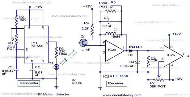
Here is the circuit diagram of an infrared motion detector that can be used to sense intrusions.Infra red rays reflected from a static object will be in one phase, and the rays reflected from a moving object will be in another phase.The circuit uses this principle to sense the motion.
The IC1 (NE 555) is wired as an astable multivibrator .The IR diode connected at the output of this IC produces infrared beams of frequency 5Khz.These beams are picked by the photo transistor Q1 .At normal condition ie; when there is no intrusion the output pin (7) of IC2 will be low.When there is an intrusion the phase of the reflected waveforms has a difference in phase and this phase difference will be picked by the IC2.Now the pin 7 of the IC 2 goes high to indicate the intrusion.An LED or a buzzer can be connected at the output of the IC to indicate the intrusion.
Circuit diagram with Parts list.

- Comparators IC2a and IC2b are belonging to the same IC2 (LM1458).So the power supply is shown connected only once.No problem.
- When there is disturbance in the air or vehicles passing nearby,the circuit may get false triggered.
- POT R5 can be used for sensitivity adjustment.
www.indianengineer.wordpress.com
www.indianengineer.wordpress.com
email Us at
Freshersblog@gmail.com
Metal Detector Circuit
Metal Detector Circuit
Description
This is the circuit diagram of a low cost metal detector using a single transistor circuit and an old pocket radio..This is nothing but a Colpitts oscillator working in the medium band frequency and a radio tuned to the same frequency.First the radio and the circuit are placed close.Then the radio is tuned so that there is no sound from radio.In this condition the radio and the circuit will be in same frequency and same frequencies beat off to produce no sound.This is the set up.When the metal detector circuit is placed near to a metal object the inductance of its coil changes , and so do the frequency of oscillations.Now the two frequency will be different , there will be no canceling and radio produces a hissing sound.The metal is detected.
Note
To make L1 make 60 turns of 36SWG enameled Copper wire on a 1 cm PVC tube.
Powering the circuit using a adapter rather than a battery induces noise. It is always good to power radio projects from battery.
Circuit Diagram & Parts List .
CONTACT INDIAN ENGINEER’S FOR ANY DETAILS ON THE PROJECTS
JUST LEAVE US AN EMAIL AT freshersblog@gmail.com
About
Welcome IndianEngineer’s!
Call Us Today 09911-4400-74 for Special Discount.
CLICK HERE To Book your Project Now!
Connect with Us on FACEBOOK Twitter,


FOR LIST OF PROJECTS FOR FINAL YEAR
LIST OF PROJECTS


- Freshers Wanted
- Download Free Presentation Demo

Chat with IndianEngineer’s
 Using Global Positioning System (Gps)")

 Using Global Positioning System (Gps)")

LIVE CHAT
 Government Jobs
- An error has occurred; the feed is probably down. Try again later.
-

CLICK HERE


Book your projects Now
IES,GATE PSU COACHING CLASSES


Recent Comments By You
Aamir Shaikh on Infrared motion detector … Mohit on Final Year Projects Kanwal NAZ on Latest List of ASP .NET projec… Kanwal NAZ on Latest List of ASP .NET projec… noor on Latest List of ASP .NET projec… Rksaini on Latest List of ASP .NET projec… suma on Latest List of ASP .NET projec… sava on Latest List of ASP .NET projec… Nitin on BOOK YOUR PROJECT NOW” A… Nitin on BOOK YOUR PROJECT NOW” A… sahana on Latest List of ASP .NET projec… Aditya Kakade on Microcontroller Based Projects hadi on Latest List of ASP .NET projec… writing a reaction p… on Final Year Projects krishna on Latest List of ASP .NET projec… - Banking Jobs
- An error has occurred; the feed is probably down. Try again later.
- Freshers Jobs
- Benefits Provided to BSNL Employees New Recruitee
- Limited Internal Competitive Examination (LICE) for promotion of JTO(Telecom) to the grade of SDE(Telecom)
- Limited Internal Competitive Examination (LICE) for Kanishth Rajbhasha Adhikari for the Recruitment Year -2023
- LICE for promotion of Group ‘C’ Employees to the grade of Junior Telecom-officer (Telecom) [JTO (T)] in BSNL under 50% internal quota for vacancy year 2022
- Limited Internal Competitive Examination (LICE) for promotion to the grade of Telecom Technician (TT) BSNL under 50% internal quota for vacancy years 2020 and 2021
- Limited Internal Competitive Examination (LICE) for promotion to the grade of Junior Engineer (T) BSNL under 50% internal quota for vacancy year 2021 Date of Exam 27.08.2023.
- Scheme and Syllabus for LICE SDE Telecom BSNL to AGM Telecom BSNL Internal Examination Dated 16.05.2023
- Limited Internal Competitive Examination (LICE) for promotion from SDE (Telecom) to the grade of Assistant General Manager (AGM/DE) on regular basis for vacancy 2023 under 33% LICE Competitive Quota—Indicative Notification of Exam thereof reg.
- BSNL JAO 2017 All Merit Lists and Corregendums and Results combined
- BSNL Management Trainee 2019 Question Paper, Questions and Correct Answers!
- projects world projects
- Latest Embedded Projects from Projectsbazaar.in
- VHDL Project’s List with Rating
- Free Synopsis Prepaid Energy Meter
- SOLAR SUN TRACKER
- RFiD Based Door Access Control
- SCHEMATIC DIAGRAM HOME SECURITY SYSTEM + SMS THROUGH GSM MODEM
- AUTOMATIC ROOM LIGHT CONTROL WITH BI DIRECTIONAL VISITOR COUNTER
- MICROCONTROLLER BASED MULTI STORY CAR PARKING SYSTEM
- Cell Phone Operated land Rover ( landrover )
- Electronic Voting Machine
Advertise


