Microcontrollers & Use in Embedded Technology
Its fun programming and working with microcontrollers. With microcontrollers you can create a piece of hardware which acts according to your wish (obviously with some limitations !). Examples are you can flash a LED, drive a 7 segment display, print text on a LCD, receive signals from a remote control, control electrical appliances of your room, build a robot that follows a line on the floor and avoids obstacles coming in between, frequency meter and infinitely many more..

BSNL JTO COACHING
Basically a Microcontroller is a mini computer with CPU, Memory, I/O lines etc. Microcontrollers are much better for smaller embedded systems than their ancestors i.e. microprocessors, if you are developing a system using microprocessor, then your hardware or circuit will be more complex whereas if you choose a microcontroller, your hardware becomes simple because all the necessary peripherals such as RAM, ROM, TIMERS, I/O ports etc are embedded in a microcontroller. Therefore it is also called a mini computer on a chip. Now we will start with interfacing various devices to microcontrollers (Assuming you have basic knowledge of 8051 architecture and assembly programming and also C). I have chosen 8051 microcontroller due to its simplicity in architecture and assembly language, and learning 8051 chip is much easier than other microcontrollers if you don’t have any prior knowledge on microcontrollers. For more detailed information of hardware architecture and assembly language of 8051 microcontroller you can refer hardware manual and instruction set from ATMEL’s homepage.
Most of the projects and tutorials published here are based on Atmel’s AT89S52 microcontroller, it is a 8- bit microcontroller with 8051 architecture, comes in a 40 pin DIP, contains all necessary peripherals required for a hobby project. Now for a microcontroller to be operational the minimum hardware you need is a crystal oscillator, power supply, power on reset etc. So I have come up with a very simple development board to carry on the projects and interfacing tutorials published here. (Note: This development board is not compulsory; you can also rig up the circuits in breadboard since most of the circuits are simple). You can construct the development board on a general purpose circuit board. (Soon I will be publishing PCB layout for this).
We will start with interfacing microcontroller with LED’s, Displays, Motors, Relays etc.
· Interfacing 7 segment Display
· Interfacing multiple 7 segment displays
· many more to come…
In order set up your simple home lab, you need
· keil or any other assembler/compiler.
· ISP programmer circuit
· ISP programmer software
· Target hardware (your development board or circuit).


Microcontroller 7 Segment Interfacing
Seven segment display is a basic type of display which can display numbers from 0 to 9. The circuit for interfacing single 7 segment display is shown below.
Driving a 7 segment display is as simple as flashing LEDs, but here we are flashing 7+1 LEDs. The 7 segment display module has 8 LEDs (7 segments to display number and one segment for decimal point or dot) arranged in a particular manner as shown in image below.
By driving (in the sense controlling ON and OFF conditions) these LEDs in various combinations, we can display the numbers 0 to 9. There are basically two types of 7 segment displays, they are common cathode and common anode. In common cathode, the cathodes of all the LED segments are connected together, we should apply a logic 1 or high input to a segment pin to light up that particular segment, and in common cathode the case is opposite. Table below shows the combinations of inputs to be applied to 7 segment display for digits 0 to 9.
| For common cathode displays | ||
| Digit | binary input value | hexadecimal input value |
| 0 | 11111100 | FC |
| 1 | 01100000 | 60 |
| 2 | 11011010 | DA |
| 3 | 11110010 | F2 |
| 4 | 01100110 | 66 |
| 5 | 10110110 | B6 |
| 6 | 10111110 | BE |
| 7 | 11100000 | E0 |
| 8 | 11111110 | FE |
| 9 | 11110110 | F6 |
| For common anode displays | ||
| Digit | binary input value | hexadecimal input value |
| 0 | 00000011 | 03 |
| 1 | 10011111 | 9F |
| 2 | 00100101 | 25 |
| 3 | 00001101 | 0D |
| 4 | 10011001 | 99 |
| 5 | 01001001 | 49 |
| 6 | 01000001 | 41 |
| 7 | 00011111 | 1F |
| 8 | 00000001 | 01 |
| 9 | 00001001 | 09 |
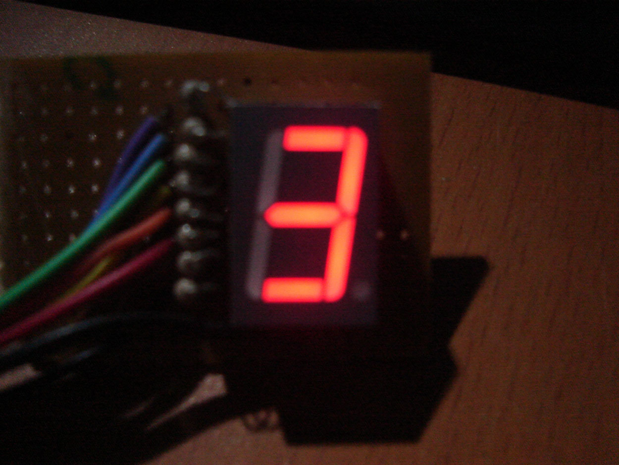
The images shown below are the photographs of 7 segment add-on board for my microcontroller board, I have included one 7 segment in the current version of my development board, so if you are using that circuit then you don’t need an external 7 segment display board. Click on the image to enlarge.
The assembly language source code for interfacing 7 segment display is given below.
| ;************************************************* ; ;Program: Driving seven segment display ;Author: Srikanth ;Website: http://shree-electronics.com/ ;Description: Displays numbers 0 to 9 on ;the LED seven segment display continuously ; ;************************************************* ;Declarations ;************************************************* ;Main program main:mov r0,#08h again:mov port,#11111100b ;’0′ ;************************************************* delay:mov r2,#0ffh ;delay subroutine ;************************************************* end |
Microcontroller LEd InterFacing
The first thing usually done while learning any microcontroller or embedded system is blinking an LED. The circuit below shows the circuit for Interfacing an LED.
note: Since the circuit diagram dimensions are big, your browser may fit the image to window size, if you are using Internet explorer, then an expander tool will be displayed on the bottom right corner, if you are using firefox , then when you move the mouse pointer over the image a magnifier tool will be displayed.
Here an LED is connected to the first pin of port0 (P0.0). The assembly program given below is simple and self explanatory.
| ;************************************************* ; ;Program: Blinking LED. ;Author: Srikanth ;Website: http://shree-electronics.com/ ;Description: Blinks an LED connected to P0.0 ;continuously ; ;************************************************* led equ P0.0 org 00h delay:mov r7,#0ffh ;delay subroutine end |
The program is purposely made lengthy in order to explain some programming techniques such as subroutine, loop etc.
Interfacing Relays
Relays allow us to control the high power circuits or instruments using low power circuits and voltage levels such as output of microcontrollers. Interfacing relays to 8051 or any other microcontroller is just simple as controlling a LED. A relay consists of a coil which is driven by low power circuits such as microcontrollers in order to control high power ac circuits through output switches. Normally there are two types of switches in a relay, they are Normally Open (NO) and Normally Closed (NC) contacts. ‘NO’ contacts are open when relay is not activated where as the ‘NC’ contacts are closed, when relay is activated by supplying power to the input coil, the ‘NO’ contacts are now closed and the ‘NC’ contacts are open. The circuit diagram for interfacing relay to a 8051 microcontroller is shown below. The assembly program for interfacing relay is given below.
|
Interfacing Keybord With Microcontroller
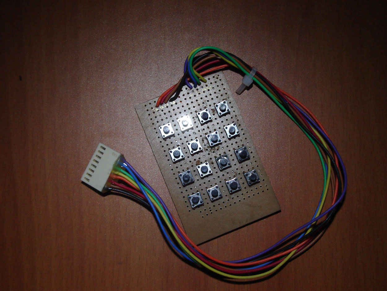
Keyboard is a basic and essential element of an embedded or microcontroller system. For small and hobby projects a 4×4 (hex) matrix keyboard is sufficient. The keys in the matrix keyboard are arranged in a matrix arrangement in order to utilize the port pins of the microcontrollers efficiently. Here we can interface 16 keys by using just 8 pins of microcontroller. This is shown in the circuit diagram.
As shown in the circuit diagram, the rows are connected to 4 pins of a port, the columns are connected to other four pins, we configure rows as input and columns as output. By grounding one column and setting high all other columns, now by observing the status of the rows, we can come to know which button is pressed. For example, if we ground the first column and if the first row is low, then the first button is pressed. We know that microcontrollers are really fast, therefore they can detect the key press in microseconds, if we hold the switch for long time (for a microcontroller long time is in milliseconds), the microcontroller is triggered more than once, also there is a problem of switch debounce because of the spring action of the switch. To eliminate these problems we should introduce some amount of delay after every key press. The assembly source code for the circuit is given in the table below.
Circuit diagram for interfacing 4×4 keyboard to 8051(89s52):
My prototype for connecting to the main development board:
The assembly program for interfacing 4×4 keyboard:
| ;************************************************* ;Program: Blinking LED. ;Author: Srikanth ;Website: http://shree-electronics.com/ ;Description: Displays the button pressed on the ;keyboard on a 7 segment display. ; ;keyboard format: 0 1 2 3 ; 4 5 6 7 ; 8 9 A B ; C D E F ;************************************************* ;Declarations rw0 equ P2.0; rw1 equ P2.1; rw2 equ P2.2; rw3 equ P2.3; cl0 equ P2.4; cl1 equ P2.5; cl2 equ P2.6; cl3 equ P2.7; ;************************************************* ;Main program org 00h org 30h ;************************************************* row0: mov dptr,#led_data row1: mov dptr,#led_data+4h row2: mov dptr,#led_data+8h row3: mov dptr,#led_data+0ch over: ret ;************************************************* ;************************************************* |
8051 serial port
Start > All programs > Accessories > Communications > Hyper Terminal
2.Specify a name for the connection
3.Configure the connection parameters
Select the port of your PC i.e.COM1, COM2 etc., click OK
Set baud rate as required, and change Flow control to none
The connected in the bottom shows the status of the connection.
HyperTerminal displays only the character or data received, not the one you typed to send.
You are ready with level converter hardware and HyperTerminal, now its time for testing your level converter hardware. For testing purpose, just interconnect the Tx and Rx pins of the level converter, and type something in the HyperTerminal, you will see the echo.
8051 USART uses dedicated buffer register SBUF, the mode and other settings of the serial port such as number of stop bits etc. is determined by the contents of SCON register. Timer 1 should be initialized to 8-bit auto reload, and its content determines the Baud rate of the 8051 serial port. Read datasheet to know more about different modes of UART.
Connecting the Microcontroller:
About
Welcome IndianEngineer’s!
Call Us Today 09911-4400-74 for Special Discount.
CLICK HERE To Book your Project Now!
Connect with Us on FACEBOOK Twitter,


FOR LIST OF PROJECTS FOR FINAL YEAR
LIST OF PROJECTS


- Freshers Wanted
- Download Free Presentation Demo

Chat with IndianEngineer’s
 Using Global Positioning System (Gps)")

 Using Global Positioning System (Gps)")

LIVE CHAT
 Government Jobs
- An error has occurred; the feed is probably down. Try again later.
-

CLICK HERE


Book your projects Now
IES,GATE PSU COACHING CLASSES


Recent Comments By You
Aamir Shaikh on Infrared motion detector … Mohit on Final Year Projects Kanwal NAZ on Latest List of ASP .NET projec… Kanwal NAZ on Latest List of ASP .NET projec… noor on Latest List of ASP .NET projec… Rksaini on Latest List of ASP .NET projec… suma on Latest List of ASP .NET projec… sava on Latest List of ASP .NET projec… Nitin on BOOK YOUR PROJECT NOW” A… Nitin on BOOK YOUR PROJECT NOW” A… sahana on Latest List of ASP .NET projec… Aditya Kakade on Microcontroller Based Projects hadi on Latest List of ASP .NET projec… writing a reaction p… on Final Year Projects krishna on Latest List of ASP .NET projec… - Banking Jobs
- An error has occurred; the feed is probably down. Try again later.
- Freshers Jobs
- Benefits Provided to BSNL Employees New Recruitee
- Limited Internal Competitive Examination (LICE) for promotion of JTO(Telecom) to the grade of SDE(Telecom)
- Limited Internal Competitive Examination (LICE) for Kanishth Rajbhasha Adhikari for the Recruitment Year -2023
- LICE for promotion of Group ‘C’ Employees to the grade of Junior Telecom-officer (Telecom) [JTO (T)] in BSNL under 50% internal quota for vacancy year 2022
- Limited Internal Competitive Examination (LICE) for promotion to the grade of Telecom Technician (TT) BSNL under 50% internal quota for vacancy years 2020 and 2021
- Limited Internal Competitive Examination (LICE) for promotion to the grade of Junior Engineer (T) BSNL under 50% internal quota for vacancy year 2021 Date of Exam 27.08.2023.
- Scheme and Syllabus for LICE SDE Telecom BSNL to AGM Telecom BSNL Internal Examination Dated 16.05.2023
- Limited Internal Competitive Examination (LICE) for promotion from SDE (Telecom) to the grade of Assistant General Manager (AGM/DE) on regular basis for vacancy 2023 under 33% LICE Competitive Quota—Indicative Notification of Exam thereof reg.
- BSNL JAO 2017 All Merit Lists and Corregendums and Results combined
- BSNL Management Trainee 2019 Question Paper, Questions and Correct Answers!
- projects world projects
- Latest Embedded Projects from Projectsbazaar.in
- VHDL Project’s List with Rating
- Free Synopsis Prepaid Energy Meter
- SOLAR SUN TRACKER
- RFiD Based Door Access Control
- SCHEMATIC DIAGRAM HOME SECURITY SYSTEM + SMS THROUGH GSM MODEM
- AUTOMATIC ROOM LIGHT CONTROL WITH BI DIRECTIONAL VISITOR COUNTER
- MICROCONTROLLER BASED MULTI STORY CAR PARKING SYSTEM
- Cell Phone Operated land Rover ( landrover )
- Electronic Voting Machine
Advertise