Object Counter
Object Counter
|
Object Counter |
|||||
 Project Object Counter Block Diagram Project Object Counter Block Diagram
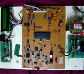
The project presented here is based on world’s most powerful microco-ntroller based on intel’s mcs-51 family , generally known as intel-8051. We have used its derivative atmel-89c2051. Operation: A pair of 38khz transmitter and a receive is used to count the objects. Counts pulses are out from the 38khd receiver which are coupled to an opto coupler. At pin 2 out put of the optocoupler is connected to microcontroller pin 8 p3.4. Ic3 an optocoupler will receive incoming count pulse at pin3 and output from pin 5 is connected to p3.4 pinof the ic2 microcontroller, Two line by 16 character on each line (2×16) is used in nibble mode and maximun count can reach upto 65536 there after it will reset to 00000. SW1 is manual reset switch to make the counter to reset to zero. Circuit is driven by 9v 500m.a. transformer connected to PCON1 Diode D1-D4 forms bridge circuit C1,c2 and c3 are filter capacitors and are part of power supply section.. Ic1 7805 is 5v regulator ic to give stablised supply to microcontroller. Ld1 is a power indication led. R1 controls the current flowing thrugh led LD1 Crystal X1 along with C5 and C6 gives the necessary clock to microcontroller. Capacitor C4 and R2 gives the required reset pulse to microcontroller.
Construction: solder all the parts provided in the kit properly. First connect the jumper wires(links) before you solder the ic sockets. Donot solder integrated circuits directly on the circuit board , it may damage the ic since you my not be experianced soldering person. So solder the ic sockets first on the circuit board. Solder smaller components first like resistance and disk capacitors, assemble the complete kit one by one. Please make sure that there are no short circuits left on to the circuit board. Connect the main supply wire with 230v ac pins at one end ,to the 9v transformer towards primary side to the other open end. . Primary side will have high resistance when checked with multimeter. Connect 2pin plug to the secondary side of the transformer(low resistance side) plug the wire to main and check the ac voltage at the plug connected to the secondary of the transformer. It should be 9v ac. Now connect the plug to the socket connected on to the circuit board. Power supply led ld1 will glow. Check the voltage at the output of the regulator. It should be perfactly 5v dc. Check the voltage at the power supply pins of all the sockets mounted on circuit board it should be 5v dc.
|
Please log on to Www.indianEngineer.wordpress.com to Have more Projects or To Get Details of this Project mail us at Freshersblog@gmail.com
Thanks Team IndianEngineers


 PROJECTS TO GET COSTLY as demand will increase as exams reach so HURRY to GET it on TIME


